Introduction
Up to now, the iron-carbon phase diagram has only been considered up to a carbon content of 2.06 %. If this carbon content is exceeded, further phase transformations occur. Basically, this is also connected with a different microstructure. Iron materials below 2.06 % carbon consist of a eutectoid based microstructure (pearlite) and above 2.06 % of a eutectic based microstructure (ledeburite).
In principle, this also results in other material properties. This difference is also reflected in the subdivision into steels and cast iron. For example, ferrous materials with a lower carbon content than 2.06 % are referred to as steels and ferrous materials over 2.06 % as cast iron.
Steel has a pearlitic (eutectoid) based microstructure and cast iron a ledeburitic (eutectic) based microstructure!
This article is intended to provide more detailed information on this new microstructure of cast iron.
Cast iron
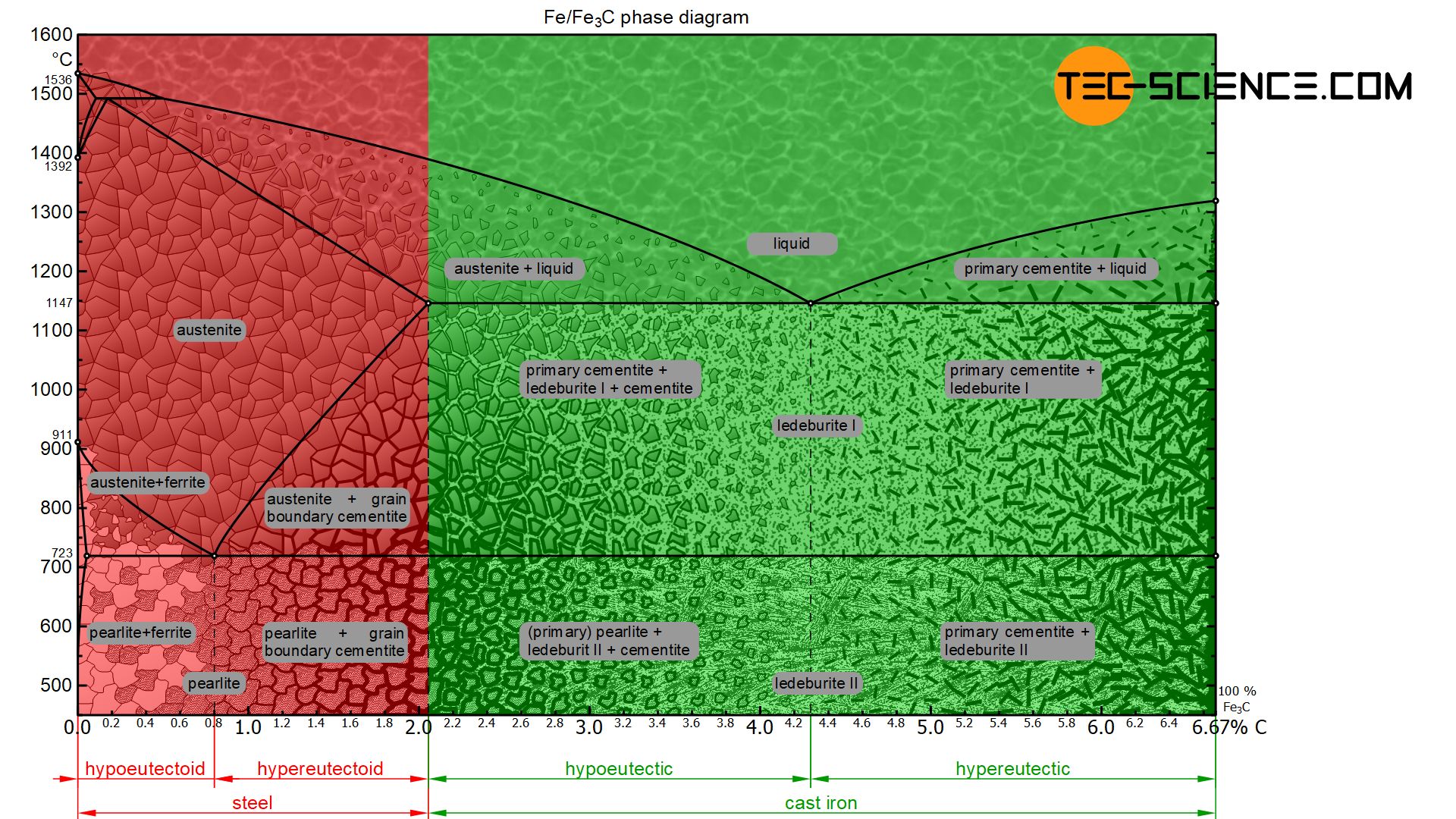
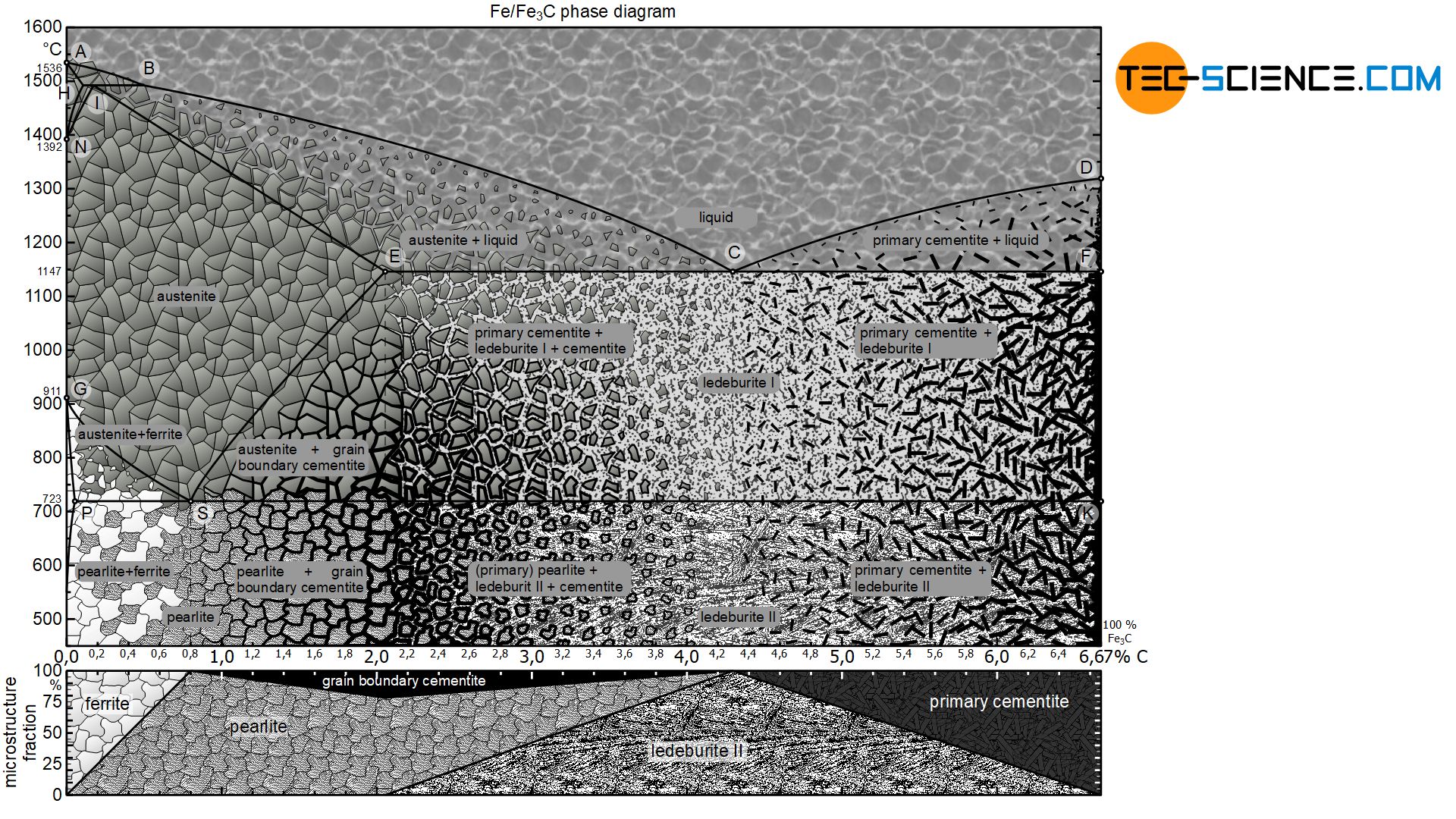
The phase diagram below shows the complete iron-carbon phase diagram of the metastable system in which the carbon is present in the microstructure in the form of cementite. The microstructure in the metastable system can therefore consist of a maximum of 100 % cementite. Since the carbon content in the cementite (\(Fe_3C\)) is 6.67 %, the metastable iron-carbon phase diagram ends at this concentration.
If only the range of the phase diagram above a carbon content of 2.06 % is considered, the fundamental difference between steels and cast iron in the solidification process becomes apparent.
At a carbon concentration of less than 2.06 %, the steel initially solidified as solid solution (homogeneous austenite microstructure) within the typical lens-shaped crystallization range in the state diagram.
In the area of cast iron, however, the phase diagram no longer shows this lenticular solidification area, but shows the typical horizontal “K” of a crystal mixture. The eutectic composition is at 4.3 % carbon, where the two liquidus lines falling from the left and right meet.
Depending on whether the iron-carbon compound solidifies as a solid solution (carbon content < 2.06 %) or as a crystal mixture (carbon content > 2.06 %), other mechanical properties of the material also result at room temperature. Alloys solidified as a crystal mixture are generally more suitable for casting processes (so-called casting alloys). In comparison, however, the solidified solid solution can be formed much better and are therefore particularly suitable for various forming processes such as bending, forging, rolling, deep-drawing, etc. (so-called wrought alloys).
For these reasons of manufacturing processing, iron-carbon compounds with a carbon content lower or higher than 2.06 % are distinguished. Below 2.06% carbon, the material is called steel. Above 2.06 % carbon, on the other hand, one speaks of cast iron, as it is particularly suitable for casting processes. In contrast to this, steels can be formed much better and are therefore forgeable in contrast to cast iron. Note that the transitions in the mechanical properties at the 2.06 % limit are always smooth!
Steels initially crystallize as solid solutions, while cast iron solidifies as crystal mixtures.
Compared to steel, cast iron therefore has a eutectic based microstructure! The reason that the steel does not form an eutectic is ultimately because steels are already solidified before the residual melt could have reached the eutectic composition. Just as steels can be divided into hypoeutectoid and hypereutectoid steels, cast iron can be divided into hypoeutectic and hypereutectic cast iron respectively.
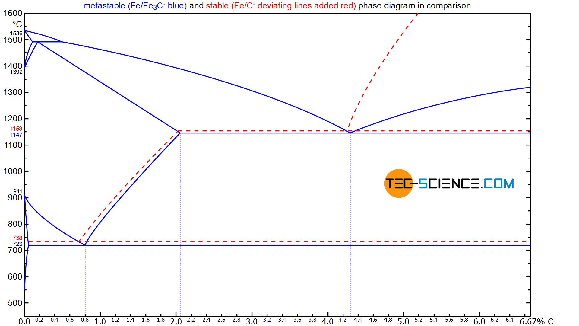
While steels generally solidify according to the metastable system due to their relatively low carbon content, cast iron can crystallize both in the metastable form (white cast iron) and in the stable form (grey cast iron). The vast majority of cast iron solidify according to the stable system due to the relatively high carbon content. Instead of the precipitation of cementite, the cast iron is then subject to graphite precipitation during solidification or cooling.
The precipitation of graphite instead of cementite affects the transformation temperatures in the phase diagram. Accordingly, a distinction must be made between the stable and the metastable iron-carbon phase diagram. The diagram below compares the metastable phase diagram (blue) and the stable phase diagram (supplemented in red).
White cast iron
In white cast iron, the cast iron solidifies in the metastable form and is thus subject to the formation of cementite. The cementite makes the fracture surface of the cast iron appear shiny white, to which the term “white” cast iron refers.
Depending on the carbon content, white cast iron can be divided into eutectic cast iron (4.3 % C), hypoeutectic cast iron (<4.3 % C) and hypereutectic cast iron (>4.3 % C). The microstructure formation and transformation during solidification and cooling of such types of cast iron are explained in more detail below.
Eutectic cast iron
If the cast iron has the eutectic composition of 4.3 % carbon, the melt solidifies as usual at a thermal arrest. Due to the strong supercooling, a fine mixture of austenite and cementite is formed. This eutectic microstructure of finely distributed austenite and cementite is also called ledeburite-I immediately after solidification.
The eutectic phase mixture of austenite and cementite immediately after solidification is called ledeburite-I!
Note that on the left side of the cast iron phase diagram (at 2.06 %) the austenite phase is applied and on the right side (at 6.67 %) the cementite phase. These phases austenite and cementite are thus ultimately the components of an A/B alloy system (A ≙ “austenite”) and (B ≙ “cementite”).
Immediately after solidification, the austenite crystals present in the ledeburite are completely saturated with carbon at 1147 °C, i.e. they show the maximum possible concentration of carbon that is soluble in the austenite. As the solubility continuously decreases according to the solubility limit (solvus line) during further cooling, the austenite crystals permanently precipitate cementite.
Finally, at 723 °C so much carbon is precipitated from the austenite that it has reached the eutectoid composition of 0.8 % carbon. Now the austenite crystals in the eutectic of ledeburite-I begin to change into pearlite at a constant temperature. The former austenite crystals have thus transformed into pearlite. This eutectic phase mixture of pearlite and cementite is now called ledeburite-II due to the changed microstructure.
The eutectic phase mixture of pearlite and cementite present at room temperature is called ledeburite-II!
Hypoeutectic cast iron
In the case of hypoeutectic cast iron, only austenite primary crystals are precipitated from the melt when the liquidus line is reached. This increases the carbon content in the residual melt. Once the carbon content has finally risen to 4.3 % at 1147 °C, the residual melt crystallizes at a constant temperature to form the eutectic (ledeburite-I). Immediately after solidification, the microstructure consists of the eutectic and the previously primarily precipitated austenite crystals.
Both the primary austenite and the austenite crystals contained in ledeburite-I precipitate cementite as cooling progresses due to the decreasing solubility of the carbon. Consequently, the microstructure in this state consists of ledeburite-I and the primary austenite embedded therein as well as the precipitated cementite. At 723 °C the eutectoid composition in the austenite crystals is finally reached (both in the primary crystals and in the eutectic).
While the ledeburite-I changes to ledeburite-II, the primary austenite grains transform to pearlite grains. Consequently, the microstructure of hypoeutectic cast iron consists of ledeburite-II with the pearlite grains embedded therein and the cementite previously precipitated from the austenite crystals.
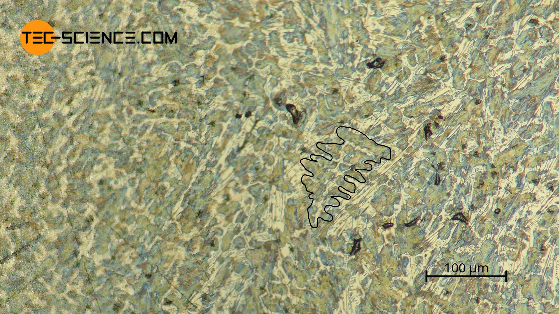
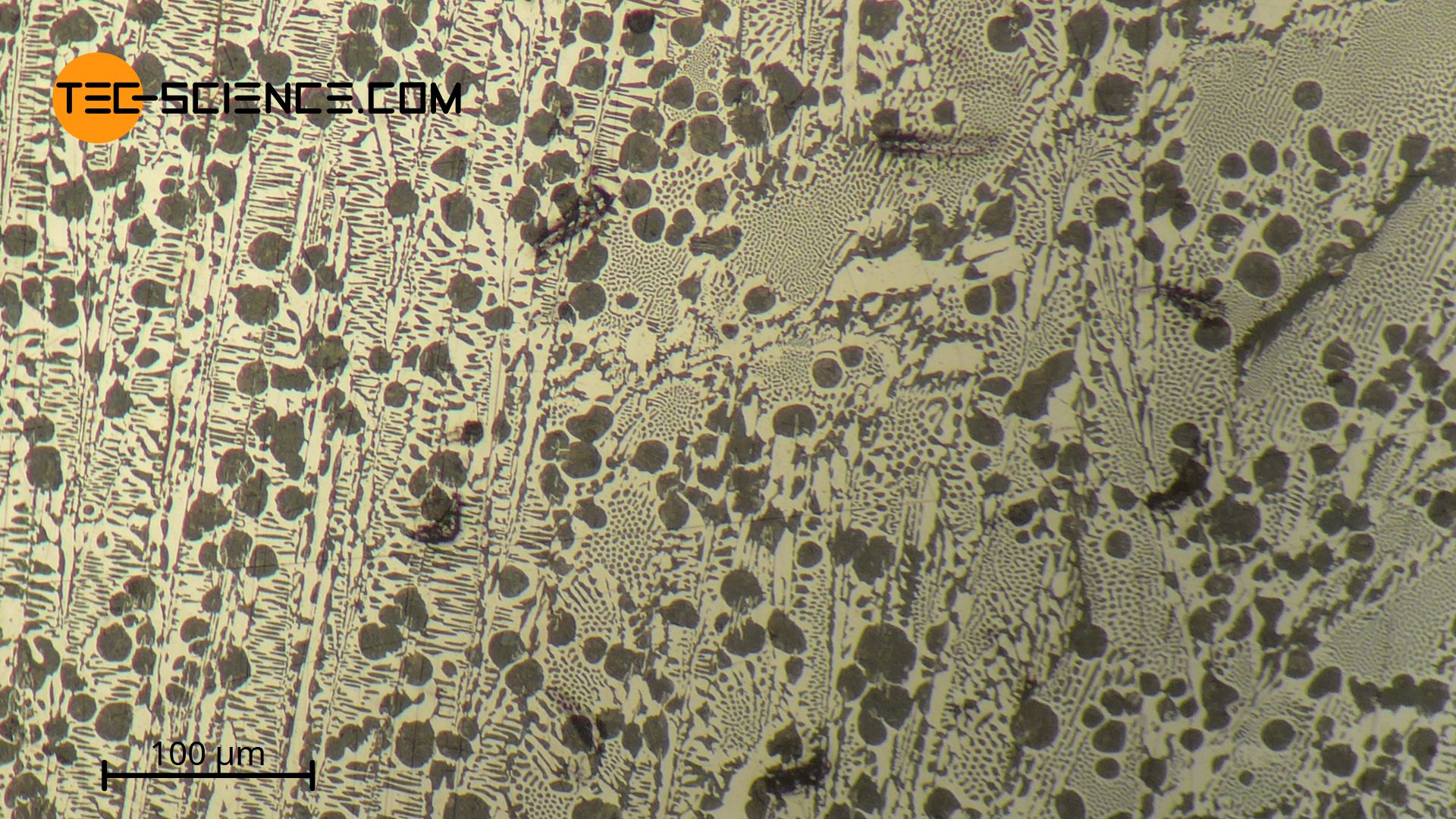
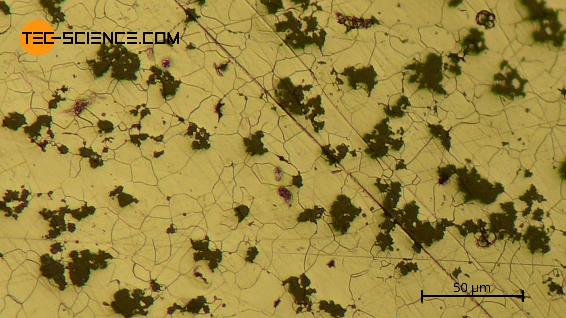
The micrograph below shows a sample of hypoeutectic cast iron with 2.7 % carbon. The \(\gamma\) solid solutions, which initially grew dendritically, can be seen, which finally turned into pearlite (dark spots). As an example, a dendrite is shown in the figure, which was cut through by the micrograph in the plane. As usual, this pearlite microstructure consists of ferrite and lamellar cementite. Between the branches of the pearlitic dendrites is the eutectic, which was also subject to the \(\gamma\)-\(\alpha\)-transformation and thus finally is present in the microstructure as leedeburite-II (dark speckled areas).
In comparison, the following microstructure shows a hypoeutectic cast iron with a higher carbon content of 3.8 %. The significantly larger proportion of eutectic matrix compared to pearlite is striking. In this case, the very fine, lamellar cementite can no longer be dissolved by light microscopy in the pearlite – it therefore appears dark as a single surface!
Hypereutectic cast iron
In hypereutectic cast iron, only primary cementite with a strip-like structure crystallises out initially during solidification. Due to the associated carbon precipitation from the residual melt, the carbon content there is reduced. Once the eutectic composition of 4.3 % carbon at 1147 °C is finally reached in the residual melt, it solidifies to the eutectic ledeburit-I.
Immediately after solidification, the microstructure consists of the primary precipitated strip-cementite, which is embedded in the surrounding ledeburite-I. The austenite contained in the eutectic finally undergoes cementite precipitation when the temperature is lowered. If the carbon content in austenite has dropped to 0.8 % at 723 °C, it begins to convert to pearlite. In this way the eutectic ledeburit-I becomes ledeburit-II.
The cooled hypereutectic cast iron microstructure thus consists at room temperature of the primarily precipitated cementite strips which bed in the eutectic of ledeburit-II.
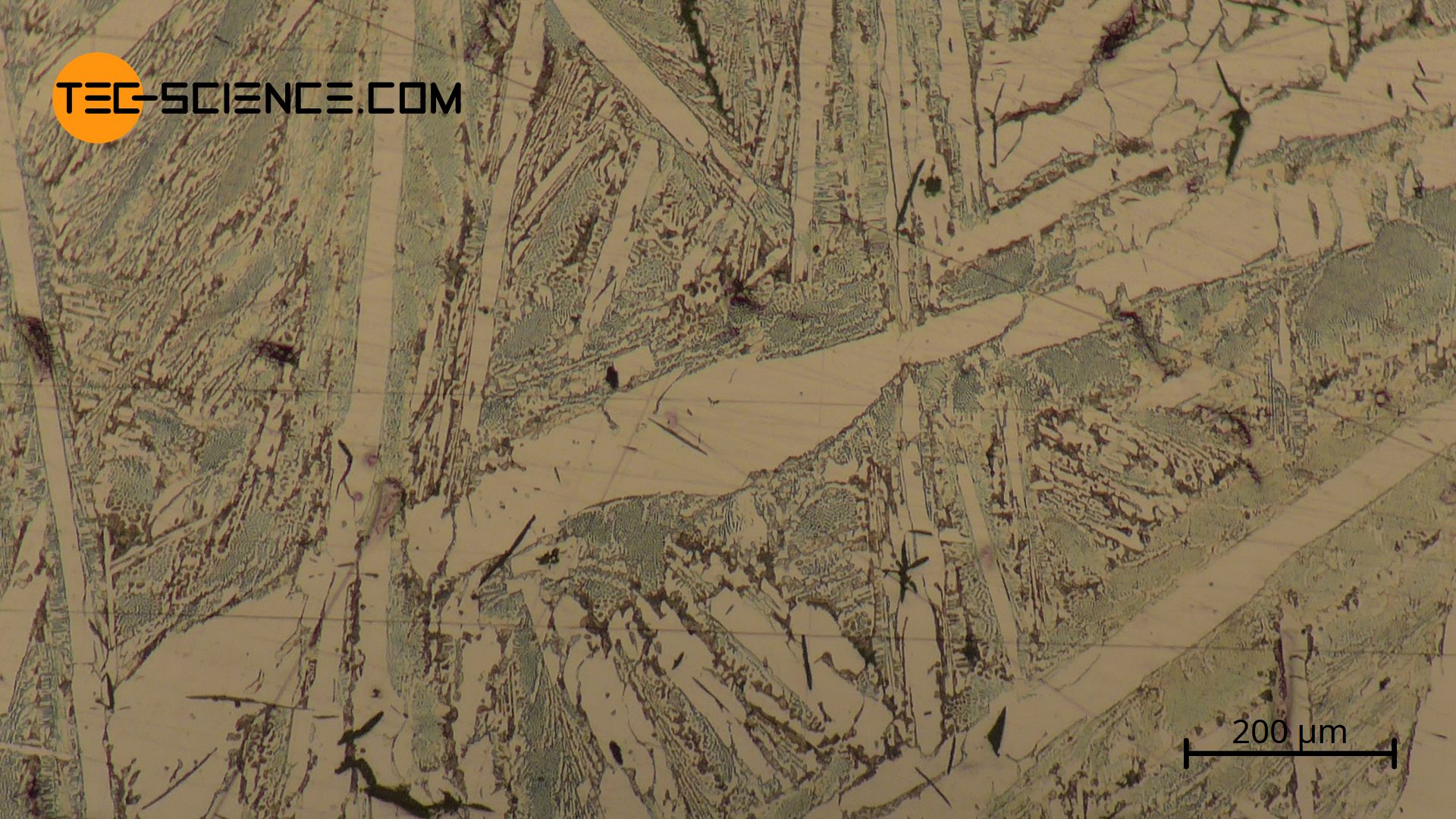
The micrograph below shows a hypereutectic cast iron with 5.5 % carbon. The eutectic ledeburit-II (finely patterned) and the primarily precipitated cementite needles, which due to the etching during sample production appear as white elongated stripes.
Grey cast iron
Lamellar graphite cast iron (grey cast iron)
Without any major treatment of the melt, the graphite normally crystallises in lamellar form. This is known as lamellar graphite casting. Since this ist the “normal” type of cast iron, it is simply referred to as grey cast iron.
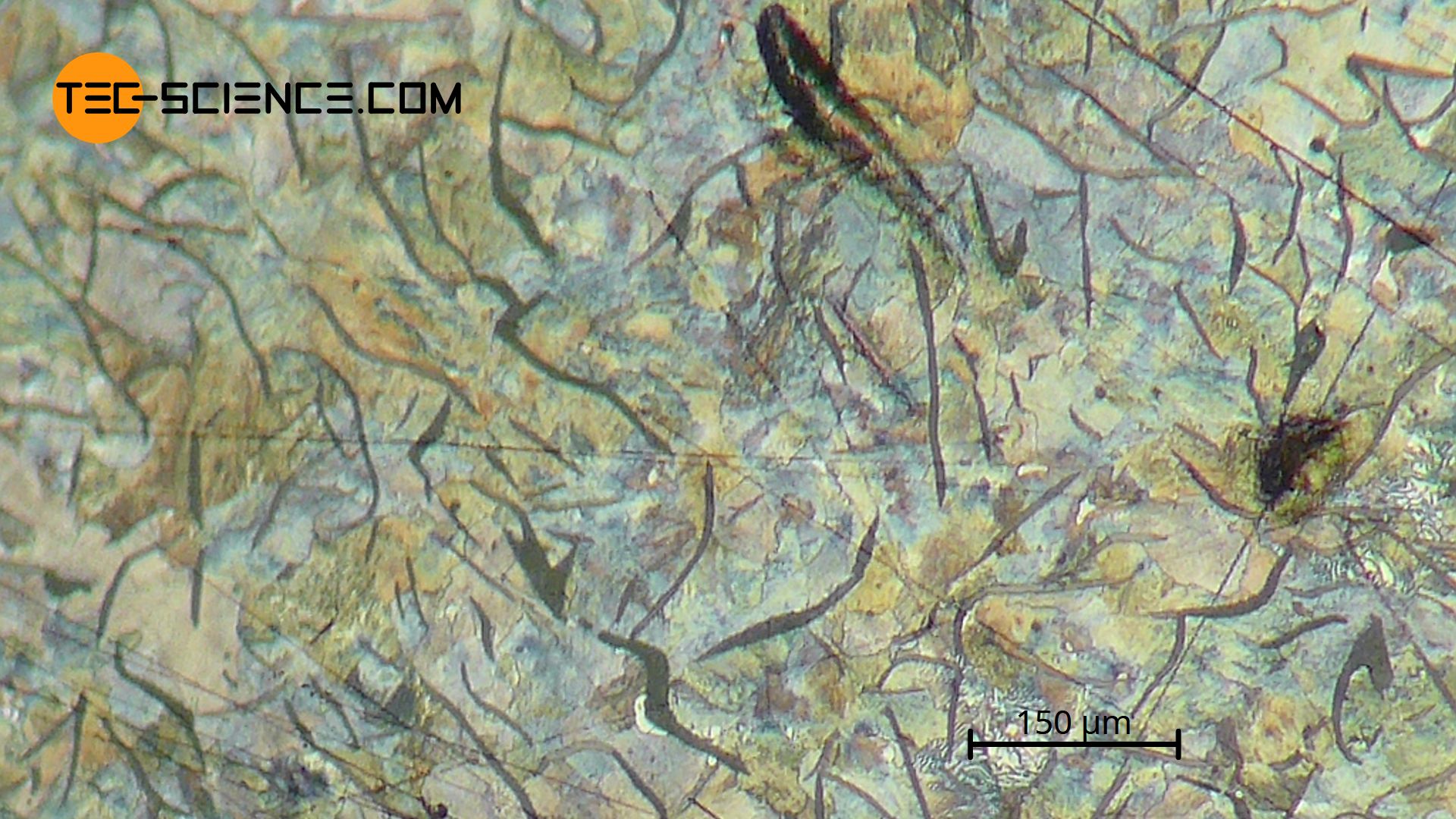
The micrograph below shows grey iron with 3.5 % carbon. The lamellar graphite can be seen (dark, large areas) surrounded by a pearlitic based microstructure (dark, fine stripes).
Cast iron with lamellar graphite has excellent casting properties and therefore offers a wide range of applications. In addition, lamellar graphite casting shows very good machinability, as the graphite also serves as a solid lubricant. In addition, the graphite lamellae in the cast structure have a special vibration damping effect. This is why lamellar graphite casting is used, among other things, as a material for highly vibration-stressed components such as machine beds or marine diesel engines.
However, the graphite lamellae have a disadvantageous effect on the tensile strength, since they act like notches (“predetermined breaking points”) in the casting structure. Therefore, lamellar graphite castings should not be subjected to tension but to pressure. The compressive strength is approx. 4 times higher than the tensile strength!
In many applications, however, the casting material has to withstand high tensile loads. Since the graphite lamellae obviously have a disturbing effect, the lamellar graphite precipitation must be specifically prevented during the solidification or cooling process. An alternative to lamellar graphite casting is nodular graphite casting as explained below.
Spheroidal graphite cast iron (nodular cast iron)
To ensure that the graphite in grey cast iron does not precipitate in the form of lamellae but spherically, the melt must be specifically treated with additives such as aluminium before solidification. A graphite precipitate in spherical form is then called spheroidal graphite cast iron or nodular cast iron.
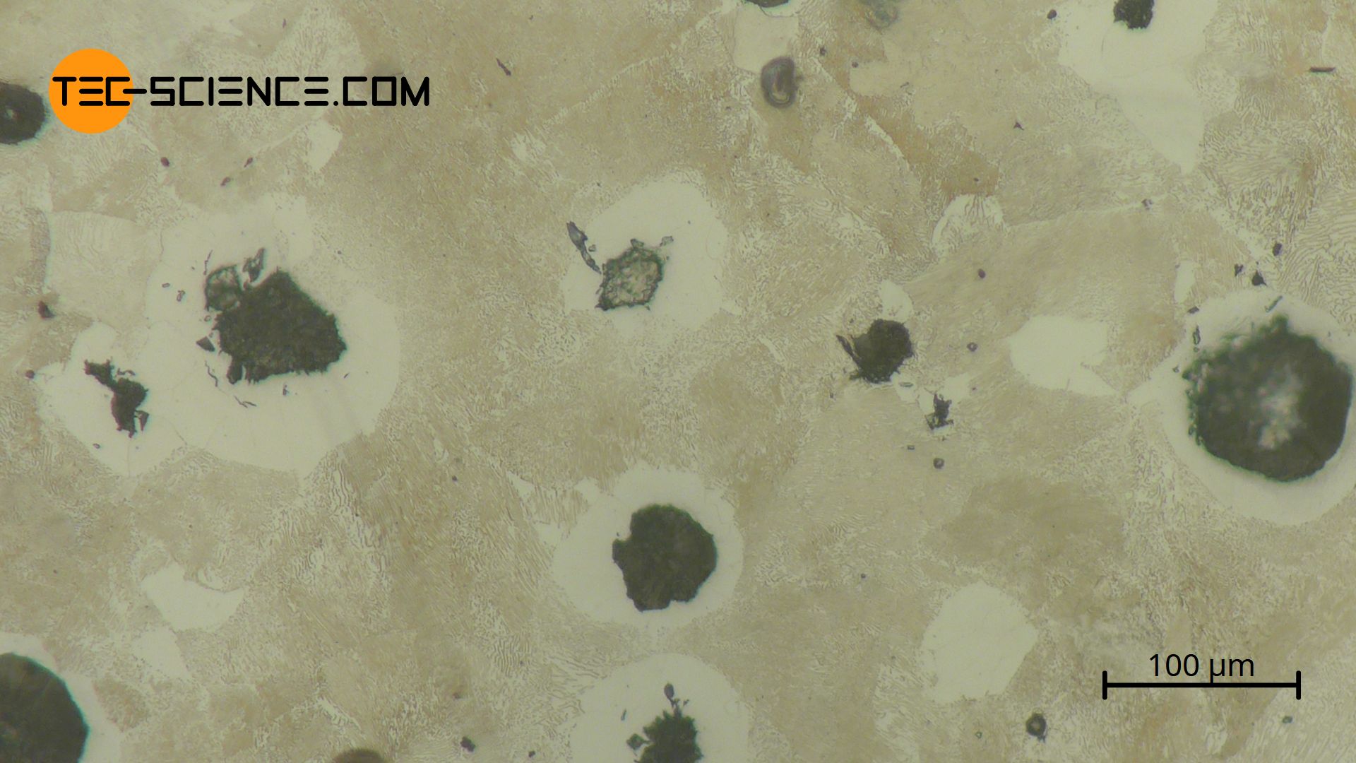
The micrograph below shows the microstructure of nodular cast iron with 3.6 % carbon. The spherically precipitated graphite (dark, roundish areas) can be seen, which has contracted from the immediately surrounding areas. The surrounding areas are almost carbon-free iron (ferrite), which therefore appears white.
The notch effect of the globular graphite is greatly reduced by the rounded shape compared to lamellar graphite. Therefore, the tensile strength of spheroidal graphite cast iron is significantly better. Since nodular cast iron is more ductile than “normal” grey cast iron, this type of cast iron is also referred to as ductile cast iron.
Vermicular graphite cast iron (compacted graphite iron)
Vermicular graphite cast iron offers (also referred to as compacted graphite iron) a compromise in the properties between lamellar and nodular graphite cast iron. The graphite is precipitated like a worm, whereby spherical graphite may also form in the microstructure to a certain extent.
The micrograph (unfortunately not yet available!) shows vermicular graphite cast iron. The graphite (black), which is precipitated like a worm, can be seen, some of which is still precipitated in a spherical form. The carbon was removed from the surrounding areas, which therefore appear white (ferrite).
Due to its good thermal shock resistance, vermicular graphite casting is particularly suitable for engine construction.
Flake graphite cast iron (malleable iron)
In the so-called flake graphite cast iron (or malleable iron), the carbon is formed into individual graphite flakes. In order to obtain this flaky microstructure, the preliminary stage of malleable iron initially solidifies graphite-free. The microstructure of this so-called white cast iron therefore contains only cementite instead of graphite. Only after subsequent heat treatment, annealing, does the metastable cementite disintegrate into its final flake graphite form and then belongs to group of the grey cast iron.
The micrograph below shows malleable iron with 2.7 % carbon. The graphite precipitated in flakes (black areas) can be seen. Carbon-free areas (ferrite) often form around the flakes, which therefore appear white. There, the carbon from the lattice has accumulated into a flake structure.
The advantage of malleable iron is its good castability with properties similar to steel, such as good toughness and strength. Malleable cast iron is used for thin-walled components, brake drums, fittings, etc.


")
