In resistance thermometers the dependence of the electrical resistance on the temperature is used to determine the temperature!
Operating principle
A further measuring principle for determining the temperature is the change in the electrical resistance of a conductor when heated. Thermometers based on such a principle are referred to as resistance thermometers or resistance temperature detector (RTD).
In resistance thermometers the dependence of the electrical resistance on the temperature is used to determine the temperature!
In RTDs, a constant electrical current flows through a measuring conductor. The currents are usually less than one milliampere to avoid excessive heating by the current. According to Ohm’s law, at a constant current the voltage at the measuring conductor varies depending on the electrical resistance (and thus on the temperature). In this way, the measured voltage or voltage change can be used to determine the temperature.
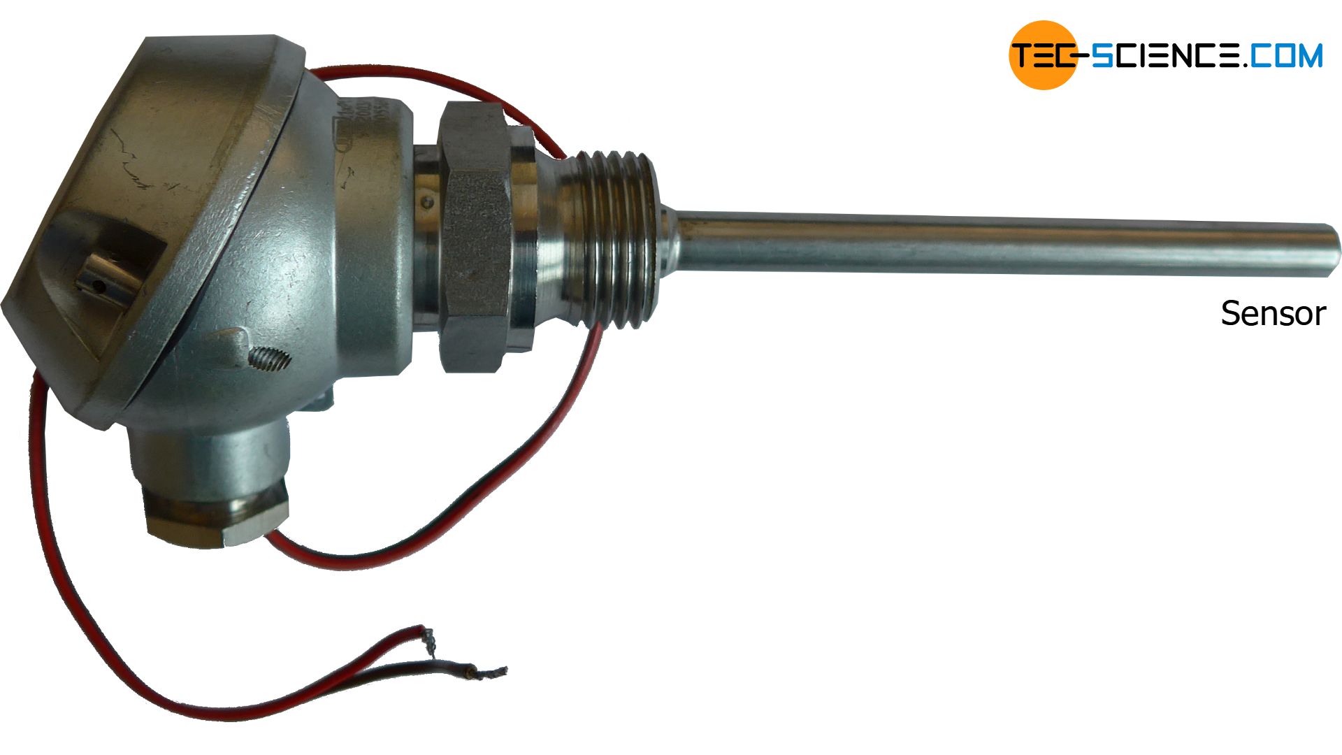
A noncorrosive platinum conductor (Pt) with a nominal resistance of 100 Ω at a temperature of 0 °C is often used as the sensing resistor. These characteristics give this type of resistance thermometer the name Pt100. The figure below shows a Pt100 with a terminal head for screwing into a pipe system to monitor the temperature.
In the measuring range between 0 °C and 100 °C, the corresponding temperature ϑ (in °C) can be calculated for the measured resistance R (in Ω) of the Pt100 as follows:
\begin{align}
&\boxed{\vartheta = \frac{R-100}{0,385} }~~\pm 0,4 °C ~~~(\text{gilt nur für einen Pt100 zwischen 0 und 100 °C)} \\[5px]
\end{align}
There are also platinum temperature sensors which have a nominal resistance of 500 Ω or 1000 Ω at 0 °C. These RTDs are referred to as Pt500 or Pt1000.
Influence of lead resistances (lead compensation)
When measuring with resistance thermometers, the lead resistance of the measuring leads must always be taken into account. After all, the measuring instrument not only measures the resistance of the actual sensing resistor, but also the resistance of the measuring leads.
In general, the higher the nominal resistance of the sensor at 0 °C, the lower the share of lead resistances on total resistance. Accordingly, the temperature measurement when using a Pt1000 is not as strongly influenced by the lead resistances as when using a Pt100. With a Pt100, the temperature measurement is falsified by about 0.5 °C per meter of connecting cable. With a Pt1000, the value is 10 times lower (0.05 °C per meter connecting cable).
The lead resistances can be compensated by four-wire sensing (also called four-terminal sensing). In this case, the current source and voltage measurement are metrologically separated from each other. This means that the voltage is no longer measured directly at the current source, where voltages across the lines would also be measured, but directly at the sensing resistor. This means that four wires are required; two for the power supply and two more for measuring the voltage.
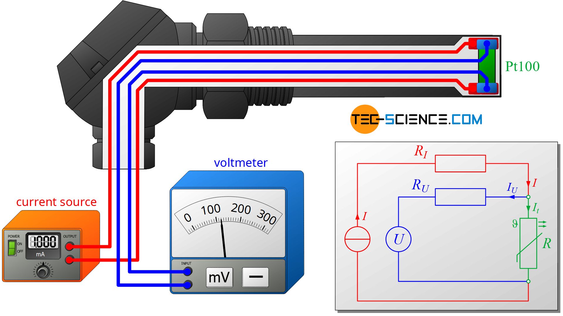
With the known constant current of the current source I and the measured voltage U directly across the resistor, the resistance value R can now be determined from Ohm’s law without lead resistances influencing the result:
\begin{align}
&\boxed{R = \frac{U}{I} } \\[5px]
\end{align}
However, such a calculation is only correct if it is ensured that the entire current of the current source actually flows through the sensing resistor! Therefore, no current may flow through the voltmeter itself. However, this is necessary for metrological reasons, as otherwise no voltage could be measured. Therefore, the only solution is to keep the influence as small as possible. For this reason, very high-resistance voltmeters are used for measuring the voltage, which “branch” only a negligibly small portion of the current.
In general, four-terminal sensing is much more complex and thus more expensive than two-terminal sensing. For this reason, two-wire sensing is usually used in practice as long as no high measurement accuracies are required.
Pros and cons
In contrast to purely indicating temperature measuring instruments such as liquid-in-glas thermometers or bimetallic strip thermometers, the electrical signal from resistance thermometers can directly be processed, combined and evaluated with other data. Resistance thermometers are also very robust and cover a wide temperature range from -200 °C up to +800 °C with high accuracy at the same time.
Depending on the application, however, the relatively large delay time of resistance thermometers can be a disadvantage, i.e. resistance thermometers require some time until they have adapted to the temperature to be measured. The thermocouples explained in the following article offer significantly shorter delay times.

?")
")


